Overview
This page describes the safety interlock system designed for the SFU Nuclear Science Laboratory by Acumen Engineering and built by United Power and its integration with safety features of the Thermo-Fisher Scientific P-385 neutron-generator. Understanding of the interlock system provides background for safe access to the exclusion zones in the laboratory and for setting up the safety interlock system for operation of the generator.
A neutron generator is a device which produces neutrons via a nuclear reaction. Typically it contains a small linear accelerator and a target system which enables a beam of nuclei to be delivered to the target at an energy sufficient to induce a nuclear reaction. The P-385 offered by Thermo-Fisher Scientific is a neutron generator which uses fusion of deuterium and tritium to produce a neutron and a helium nucleus; the components of this system are shown in Figure 1. The linear accelerator is contained in the generator tube while the high voltage up to 130 kV is supplied from the generator control box.

Safety is an important aspect of operating a neutron generator. The P-385 neutron generator includes a number of safety features that protect users and protect the unit from being operated in "out-of-bounds" conditions. The P-385 control electronics respond to system faults by shutting down neutron production within 30 seconds. This is achieved via a shutdown of the high voltage used for acceleration of the reactants. Without the acceleration high voltage, tritium and deuterium can not achieve the energy needed for fusion and the production of neutrons stops. The delay in the complete shutdown of neutron production arises from the time needed to fully discharge the accelerator high voltage potential from the initial value, which can be as high as 130 kV, to zero V.
The P-385 neutron generator safety features are summarized below. All of the safety functions produce a latching fault in the generator controls. A latching fault means that two steps are necessary to allow continued operation of the generator. First, the faulted condition must be corrected, and then the user must go to the control screen to clear the faults. The list of safety features includes:
Figure 1 shows some of the above P-385 safety features such as the interlocks on the control box, the safety lamp, as well as the Remote Emergency Shutdown button. At SFU a selection of the P-385 safety features are integrated with a permanent interlock system described in this document.
The location of the interlocked areas
Figure 2 shows the floor plan of the 6000 level of the Chemistry building and the location of the neutron-generator vault on this level between vertical (north-south) coordinate lines 73-75 and horizontal (east-west) coordinate lines Z-Ca. Figure 3 shows the floor plan of the 7000 level of the Chemistry building and location of laboratories on this level. Separation of the thin dashed-dotted coordinate lines in these figures is 10 feet.


The regions highlighted in red in Figure 2 and Figure 3 are the interlocked exclusion areas which include the neutron vault room C7078, the storage room C7078.1, the mechanical room C7086, the staircase between the C7078 neutron vault and the C7076.4 analytical/physical laboratory as well as the C7076.4 analytical/physical laboratory. The regions highlighted in yellow indicate the non-interlocked controlled area which includes analytical/physical laboratories C7076.3 and C7088. Green is used in these figures to show the non-interlocked monitored areas which include the hallways on the 6000 level south of the neutron vault and the hallways on the 7000 level north of the C7076.4 analytical/physical laboratory and south of the C7086 mechanical room.
The description of the interlock system
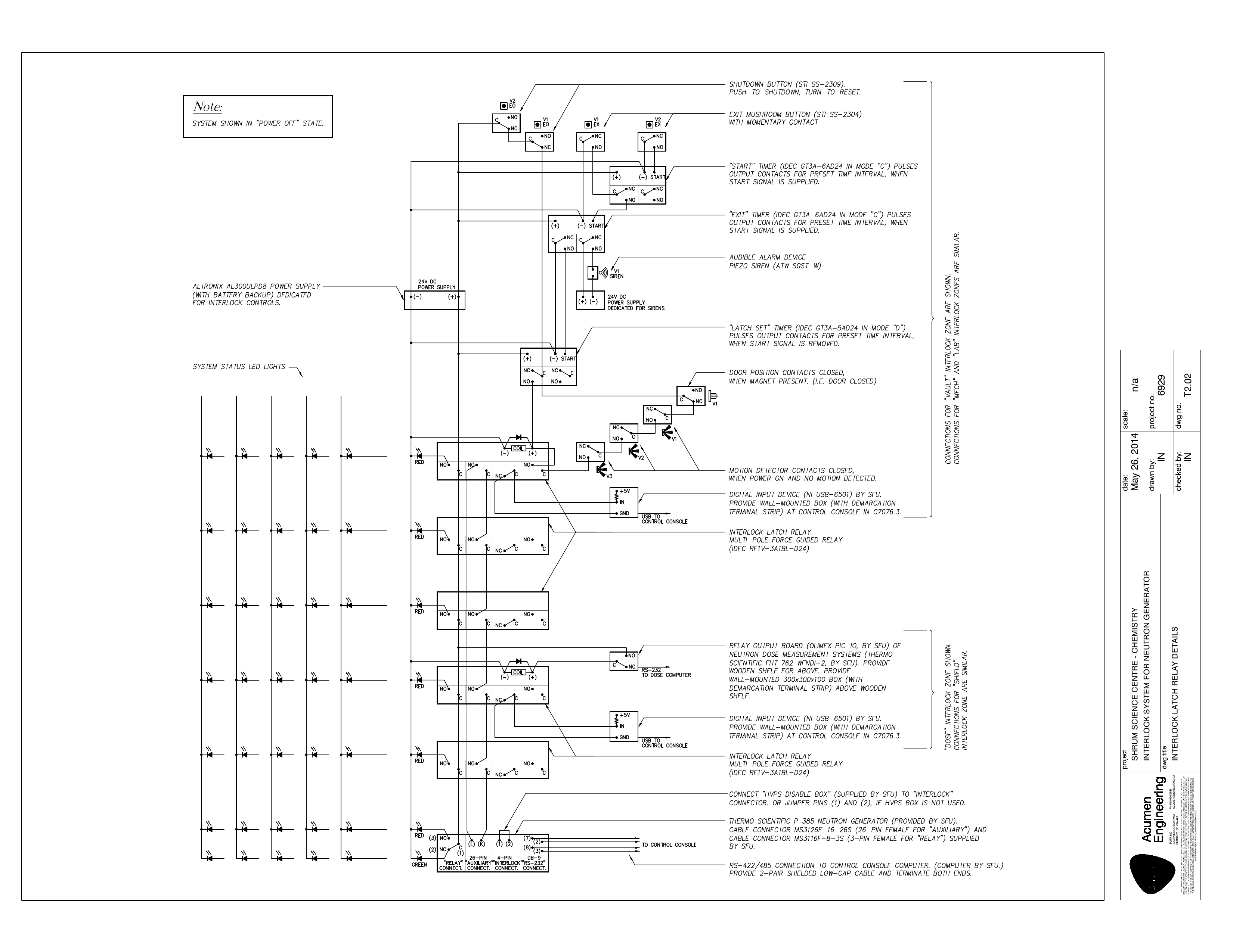
As stated above, the P-385 generator provides an interface for external interlocks. The interlock circuits are designed to inhibit the input voltage used to operate the high voltage power supply and the ion source. A connector built into the control box allows all facility interlocks (in series) to be brought into the generator for monitoring. Since all interlocks are connected in series if any single interlock faults, that breaks the series circuit and the generator automatically shuts down.
The Nuclear Science Laboratory interlock system encompasses access doors to spaces in the exclusion areas described above, protecting these areas from access when the generator is operating. It also provides an interface for a dose monitoring device which automatically shuts down the generator if a user-defined dose limit is exceeded. The interlock system accommodates sensors for monitoring water levels in moderator tanks for envisioned operation of the P-385 neutron generator with a water moderator. One of the roles of the moderator is shielding the neutron-flux, thus the intention behind interlocking water level sensors is to prevent the generator from operating with inadequate shielding in case of an unexpected drop of the water level.
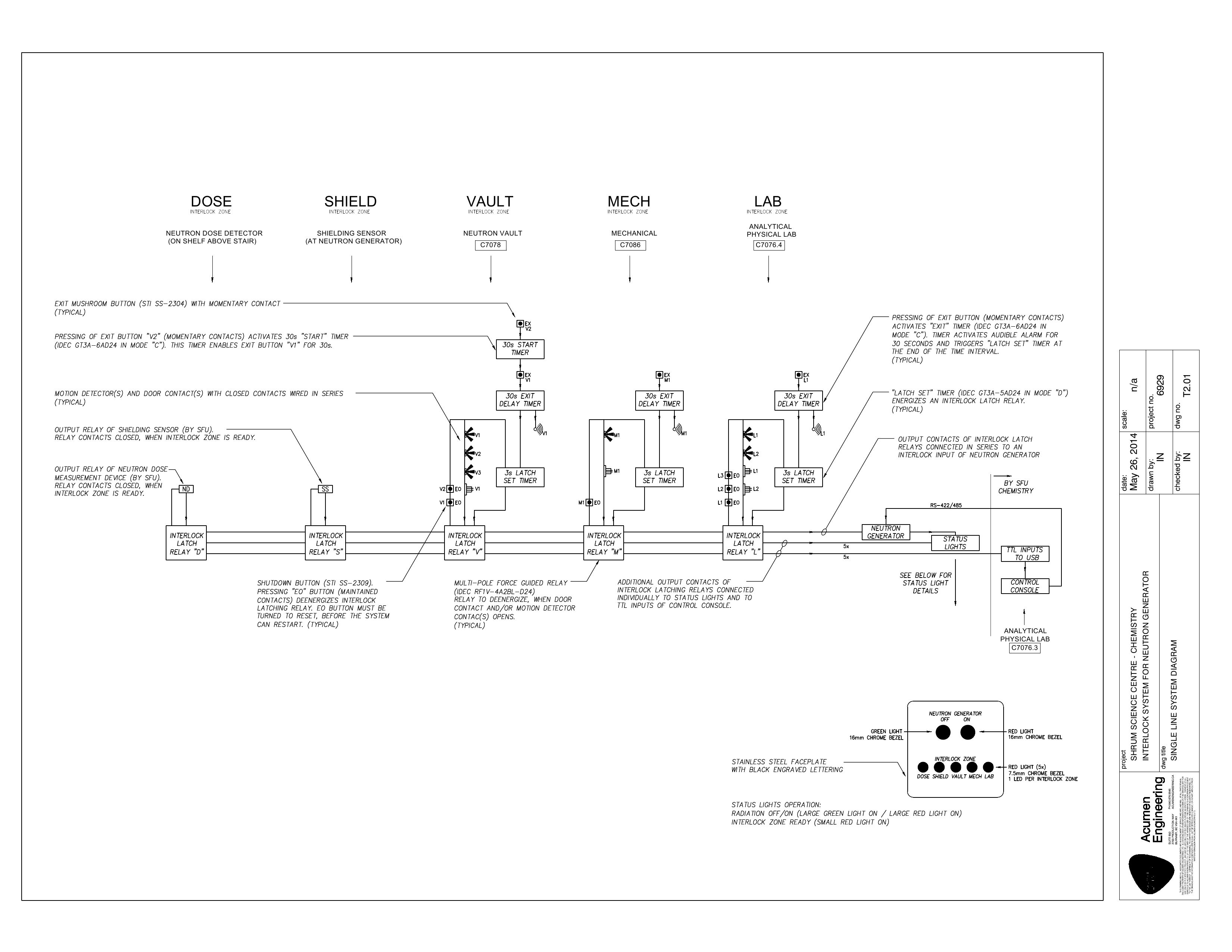
For the purpose of the design, the interlock system has been subdivided into five zones named VAULT, MECH, LAB, DOSE, and SHIELD. The VAULT zone encompasses elements of the interlock system located in the C7078 neutron vault and C7078.1 storage room with the exclusion of the moderator water tanks. The MECH zone encompasses interlock elements located in the C7086 mechanical room. The LAB zone encompasses elements of the interlock system located in the C7076.4 analytical/physical laboratory and on the staircase between the C7078 neutron vault and the C7076.4 analytical/physical laboratory with the exclusion of the dose monitoring devices. The DOSE zone encompasses the dose monitoring devices on the staircase between the C7078 neutron vault and the C7076.4 analytical/physical laboratory. The SHIELD zone encompasses elements of the interlock system monitoring water levels in the moderator tanks located in the C7078 neutron vault.
It should be noted here that at present the neutron generator is being operated without the water moderator. For these reasons the SHIELD zone is bypassed (the shunt is always interlocked). The SHIELD zone will be activated following installation of the water moderator.
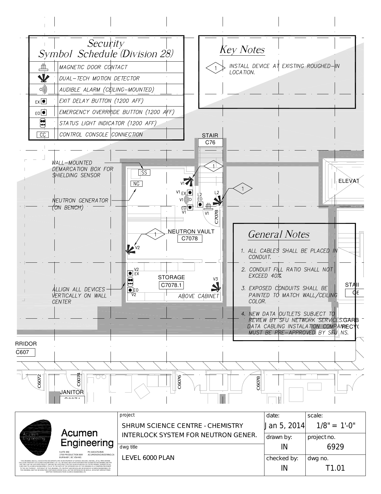
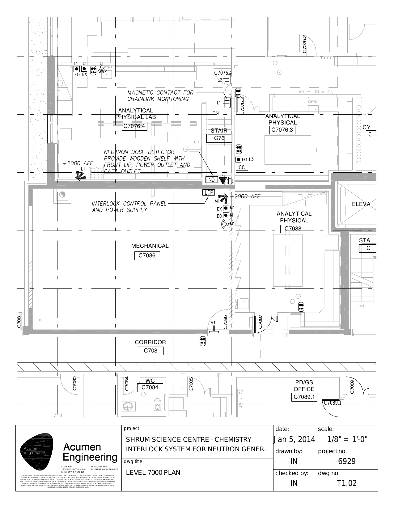
The elements of the interlock system are: magnetic door contacts, magnetic chain gate, motion sensors, emergency override buttons, exit delay buttons, audible alarms, status light indicators and interfaces for status indicator to an external computer, the external dose sensors and the external water level sensor. The location of the elements of the interlock systems are shown in Figure 4. Schematic wiring of these elements is shown in Figure 5. The design of the system assures that a fault in any of the above zones results in a fault of the whole system and subsequent shutdown of the high voltage in the neutron generator acceleration system. Moreover, any fault is a latching fault and at least two steps are necessary for removing the fault: clearing the fault of the zone and clearing the fault at the neuron-generator control.


For the VAULT, MECH, and the LAB zones there are three door interlocks installed: one at the door to the C7078 neutron vault, one at the door to the C7086 mechanical room, and one at the C7076.4 door to the analytical/physical laboratory. The detailed location of the magnetic door contacts for these three interlocks are shown in Figure 4. There is also an additional interlock chain gate installed as a part of the LAB zone at the top of the staircase between the C7076.4 laboratory and the C7078 vault; the location of the magnetic contact for the chain link is shown in the right panel of Figure 4.
There are eight infrared motion sensors installed. Six of them are shown in Figure 4. Two sensors in the C7078 neutron vault and one in the C7078.1 storage room are part of the VAULT interlock zone. The sensor in the northeast corner of the C7086 mechanical room is part of the MECH zone. The sensor at the bottom of the staircase connecting the C7076.4 analytical/physical laboratory to the C7078 neutron vault and one in the southwest corner of the C7076.4 analytical/physical laboratory are part of the LAB zone. Two motion sensors in the LAB zone are not shown in Figure 4. These are located on the east side of the C7076.4 analytical/physical laboratory near the door entrance and were added to eliminate blind spots resulting from installation of the 8π gamma-ray spectrometer of considerable size in C7076.4.
A set of Emergency Override Buttons are installed in the C7078 neutron vault, in the C7078.1 storage room, at the entrance to the C7078 neutron vault, in the C7076.4 analytical/physical laboratory, in the C7086 mechanical room, and in the C7076.3 analytical/physical laboratory where the console operating the neutron generator is located. Figure 6 shows the button at the entrance to the C7078 neutron vault. Emergency Override Buttons provide access to the Remote EMO feature of the generator and allow for a fast shutdown of the generator if need arises. Emergency Override Buttons in the C7078 neutron vault and in the C7078.1 storage room are both part of the VAULT zone. The Emergency Override Button in C7086 mechanical room is part of the MECH zone. Emergency Override Buttons at the doors to the C7078 neutron vault and in the C7076.4 analytical/physical laboratory are part of the LAB zones. The Emergency Override Button in C7076.3 analytical/physical laboratory accesses the EMO of the LAB interlock zone, specifically pressing this button breaks the interlock of the LAB zone. The location of this button in the C7076.3 analytical/physical laboratory is shown in Figure 7.


A set of Exit Delay Buttons are installed in the C7078 neutron vault, C7078.1 storage room, C7076.4 analytical/physical laboratory and C7086 mechanical room. Figure 8 shows the Exit Delay Buttons along with the Emergency Override Button in the C7086 mechanical room. Exit Delay Buttons are used for removing latching faults of the interlock zone. Exit Delay Buttons in the C7078 neutron vault and in the C7078.1 storage room are both part of the VAULT zone while these in C7086 mechanical room and C7076.4 analytical/physical laboratory are part of the MECH and LAB zones, respectively.

Figure 9 shows the location of an interface between the interlock system and the external dose monitoring sensors at the staircase between the C7078 neutron vault and the C7076.4 analytical/physical laboratory. The neutron and the gamma-ray dose is monitored on the shelf above the staircase. The Thermo-Fisher Scientific WENDI detector is used for the neutron dose monitoring while a 3"x4" NaI scintillating detector is used for gamma-ray dose monitoring. These detectors are operated by the control computer accessible at c7076-control.chem.sfu.ca which also operates a National Instruments PCI-6520 relay card with a single relay connected in series into the interlock system. The software operating the neutron and the gamma-ray detectors can turn the relay off breaking the DOSE part of the interlock if the dose limits reported by detectors are above the user-defined limits. The relay is also turned off if either the neutron monitoring detector or the gamma-ray monitoring detector stop reporting the dose measurement.

Figure 10 shows the location in the C7078 neutron vault for an interface between the interlock system and the external sensors monitoring the water level in moderator tanks. These sensors will be installed along with the moderator.

A set of Status Light Indicators are installed at the access doors to the C7076.4 analytical/physical laboratory and the C7086 mechanical room as well as within the C7076.3, C7076.4 and C7088 analytical/physical laboratories as shown in Figure 4. A schematic of a Status Light Indicator board is shown in the lower-right corner of the left panel of Figure 5 while the picture of the Status Light Indicator board at the door to the C7076.4 analytical/physical laboratory is shown in Figure 11. The Status Light Indicator has two rows, the upper labelled NEUTRON GENERATOR and the lower labelled INTERLOCK ZONE. There are two lights in the upper NEUTRON GENERATOR row, the red labelled OFF indicates that the high voltage is not applied to the accelerator head and the reaction producing neutrons can not proceed while the green labelled ON indicates that the high voltage is applied to the accelerator head and the reaction producing neutrons can proceed. The information conveyed by these lights is provided directly from the neutron-generator control box. Only one of the lights can be on at a time. There are five lights in the lower INTERLOCK ZONE row. Each of five lights represents one of the zones of the interlock systems as indicated by the DOSE, SHIELD, VAULT, MECH and LAB description below the light. If a light is on, there is no fault of the interlock system in the corresponding zone; if a light is off, there is a fault of the interlock system in the corresponding zone. All faults need to be cleared before the generator could become operational which is indicated by all five lights being on in the lower row of the Status Light Indicator.

It should be reiterated that a fault in any of the zones turns off the high voltage on the generator. However, there is a delay between the high voltage shutdown and the full discharge of the high voltage potential. The time to the full discharge can be read from the Status Light Indicators. If the neutron generator is operational the top row show the ON light on and the OFF light off, while all of the five lights in the lower row are on. In case of a fault, for example, opening doors to the C7076.4 lab the LAB light in the lower row will turn off immediately while ON light will stay on for less than 30s and after the delay the OFF light in the upper row will turn on while the ON light in the upper row will turn off. The delay in switching the lights on/off in the upper row indicates the time needed to fully discharge the high-voltage potential of the accelerator head. Thus the exclusion zones should only be entered when the upper row OFF light is on, but never when the ON light in the upper row is on.
The information conveyed by the Status Light Indicators is also made available to an external computer via a digital input/output interface provided by the interlock system for remote monitoring of the interlock status. The link to the interlock state display is provided thourgh the Safety Monitors menu. The location of the interface to the external computer is shown in Figure 9.
The interlock system is designed to result in a latching fault in the active zones with the intention to provide for the safety of the operating personnel. A latching fault means that two steps are necessary to allow the interlock system to be activated, as explained below.
For the active VAULT, MECH and the LAB zones the latching fault means that as a first step, a button located inside the corresponding exclusion space needs to be pressed. Pressing this button will activate the sound alarm informing personnel in the exclusion space that the interlock is being activated. Pressing the button will also temporarily deactivate the motion sensors while activating a timer limiting the time for executing the second step in the procedure. The second step consists of closing the door to the interlocked zone within the time limit defined by the timer. Two steps executed successfully remove the fault on the corresponding zone interlock, re-activate the motion sensors, and silence the sound alarm. Any fault after re-activation, for example opening of the interlocked doors, or motion detected within the interlocked zone, trips the interlock and requires that the two-step procedure is executed again.
For the DOSE zone the latching fault means that as a first step the origin of the dose exceeding the user-defined limits needs to be identified and handled. If the relay controling the DOSE zone was disabled because of the loss of neutron or gamma-ray dose monitors, the monitors need to be brought back online. In the second step the relay controling the DOSE zone needs to be turned on using the software available on the c7076-control.chem.sfu.ca computer.For the currently inactive SHIELD zone the latching fault will be defined at the activation of the zone.
Summary
The interlock system provides means for safe operation of the P-385 neutron generator at Nuclear Science Laboratory at Simon Fraser University. It also communicates the status of neutron production by the generator. The exclusion zones should never be accessed when the ON status light is lit on the upper NEUTRON GENERATOR row of the indicator. Exclusion zones can be accessed when the OFF status light is lit on the upper NEUTRON GENERATOR row of the indicator.