Overview
This page describes the gamma ray dose monitoring system used in conjunction with the neutron generator. This system provides the data shown in the and the pages. This system will also be developed to have the ability to shut down the generator should the gamma-ray dose surpass a user-defined limit. The rack containing the signal processing equipment for the gamma-ray dose monitoring is located on the stairwell from the C7076.4 laboratory to the C7078 Neutron Vault as shown in Figure 1 and Figure 2. The gamma-ray NaI detector is mounted next to the c7076-control.chem.sfu.ca computer as shown in Figure 3. The schematics of the Data Acquisition System is show in Figure 4, high-resolution PDF version can be downloaded from here .


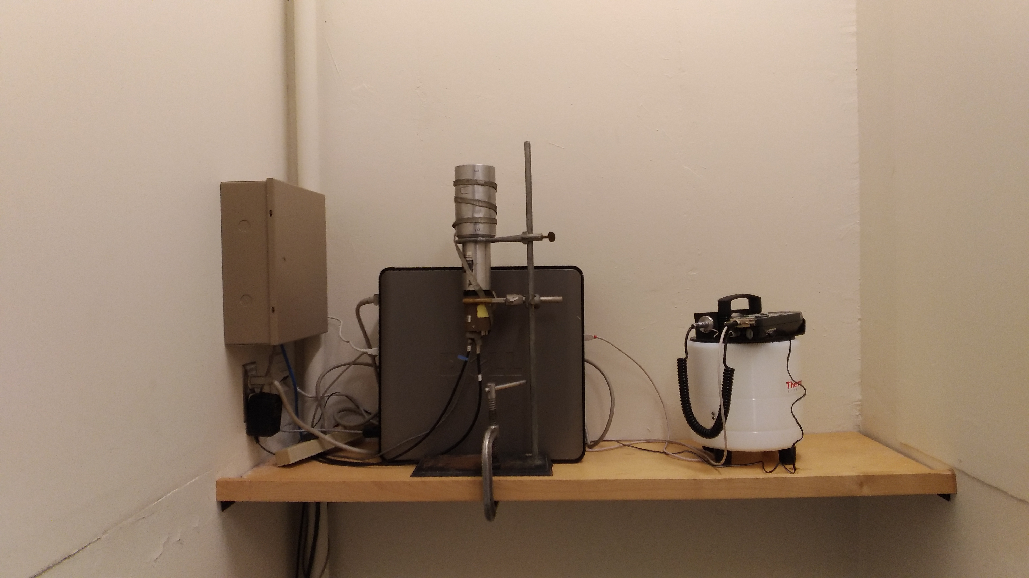

The detector
The gamma-ray monitoring detector is a Harshaw 3x4
NaI scintillating crystal
shown in Figure 5. The photomultiplier
attached to the crystal is biased at 1100 V via the
ORTEC 296 ScintiPack Photomultiplier Base
from the A-channel of an ISEG
NHQ 204M dual channel HV power supply. The ScintiPack Photomultiplier Base is
integrated with a spectroscopic preamplifier. The decay time constant for the
preamplifier signal is 50 microseconds. The power for the preamplifier is
supplied from the back DB9 connector of the TENNELEC (TC) 248 Fast/Slow amplifier
in the NIM rack shown in Figure 1 and Figure 2.

Derivation of the fast trigger and the slow signal for amplitude measurement
The signal output of the preamplifier is sent to a TENNELEC (TC) 248 Fast/Slow amplifier where the fast signal for triggering of the system is derived along with the slow signal for amplitude measurement. The settings for the module will be reported here. The fast output of the TC 248 is sent to a TENNELLEC TC 451 Constant Fraction Timing (CFD) Single Channel Analyzer (SCA) and is further processed to derive the trigger pulse for the system. The settings of the module will be reported here.
Amplitude measurement
The slow output of the TC 248 amplifier is sent to a CAMAC LeCroy 3511 Analog to Digital Coverter (ADC) for amplitude measurement and, when processed following a valid trigger, becomes the energy signal reported by the gamma-ray monitoring system. The ADC in the CAMAC crate is shown in Figure 1 and Figure 2.
Trigger processing for ADC gate derivation and measurement of the dead time
The output of the TC 451 CFD SCA is sent to the upper discriminator on a LRS 161 L Dual Discriminator (DD) module to derive two copies of the TC 451 CFD SCA signal. The first copy is sent to Channel 0 of a CAMAC Kinetics System 3615 Hex Scaler as shown in Figure 1 and Figure 2. Channel 0 of the hex scaler is thus used to count the total number of pulses derived by the CFD SCA enabling deadtime corrections from trigger counting.
The second copy of the TC 451 CFD SCA is sent to the lower discriminator on the LRS 161 L DD module which is vetoed by the NIM gate derived in the CC-USB module as described below. The output of the vetoed discriminator becomes the live trigger of the system, which is derived only when the system is ready to process the slow signal for amplitude measurement.
Three copies of the live trigger are used in the system. The first copy is sent to Channel 1 of the CAMAC Kinetics System 3615 Hex Scaler as shown in Figure 1 and Figure 2 for counting of live triggers. Two equivalent copies are sent to the CC-USB module, one to derive the veto for the lower discriminator on the LRC 161 L DD module and one to derive a NIM gate for the CAMAC LeCroy 3511 ADC. The NIM signal for deriving the LRC 161 L DD veto is provided into the I1 input of the CC-USB module, with the veto gate of 25 microsecond provided by the output O1 of the CC-USB module. The NIM signal for deriving the NIM gate for the CAMAC LeCroy 3511 ADC is provided into the I2 input of the CC-USB module, with the gate of 17.5 microsecond provided by the output O2 of the CC-USBmodule The ADC measures the amplitude of the signal within the gate and does not measure signals if the gate is not provided. Therefore only the amplitudes of the singals corresponding to the live trigger are reported by the system. The losses of the events due to the system deadtime can be accounted for from the ratio of live triggers to the total triggers counted by Channel 1 and Channel 0 of the CAMAC Kinetics System 3615 Hex Scaler.
Readout of the CAMAC modules
Upon completion of a valid measurement the ADC generates CAMAC Look-At-Me (LAM) signal on the CAMAC backplane. The result of the ADC measurement and the values of the Channel 0 and Channel 1 scaler are read out at each LAM via the CAMAC backplane by the Wiener CC-USB module. Events buffered in the CC-USB are acquired by the c7076-control.chem.sfu.ca computer running processing software. Currently, the software reports the time-stamped gamma-ray spectra taken in approximately one minute intervals along with the trigger counts for livetime corrections.